The X9110 integrates a single digital control potentiometer (XDCP) on a single chip CMOS integrated circuit. The digital control potentiometer is realized by a series array of 1023 resistance elements. Between each element are contacts connected to the wiper terminal by a switch. The location of the wiper on the array is controlled by the user through the SPI bus interface.
The potentiometer is associated with a volatile wiper counter register (WCR) and four non-volatile data registers that can be written directly to and read by the user. The contents of the WCR control the wiper position on the resistance array via a switch.
Power-up recalls the contents of the default data register (DR0) to WCR. XDCP can be used as a three-terminal potentiometer or a two-end variable resistor for a variety of applications including control, parameter adjustment, and signal processing.
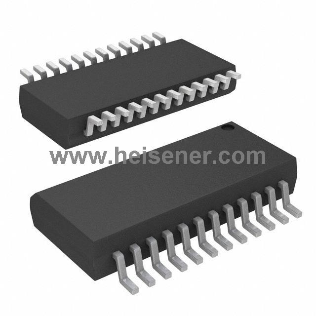
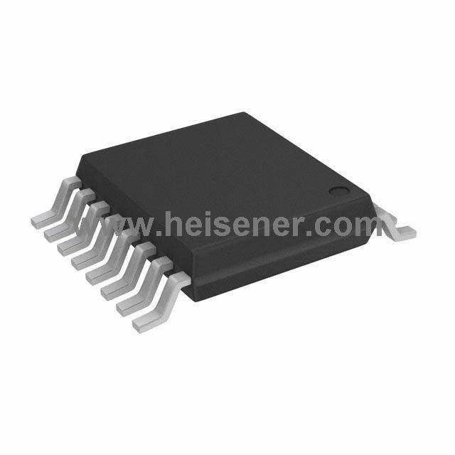
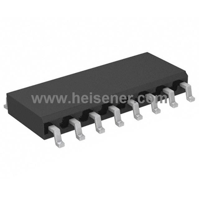
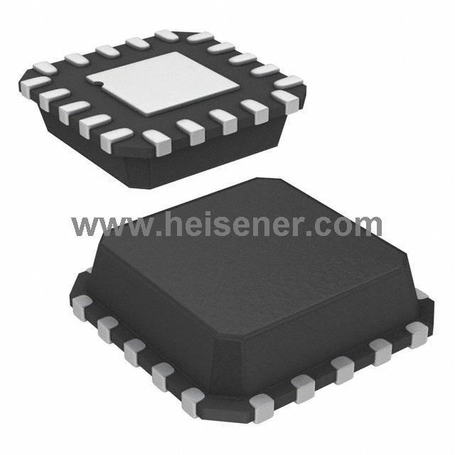
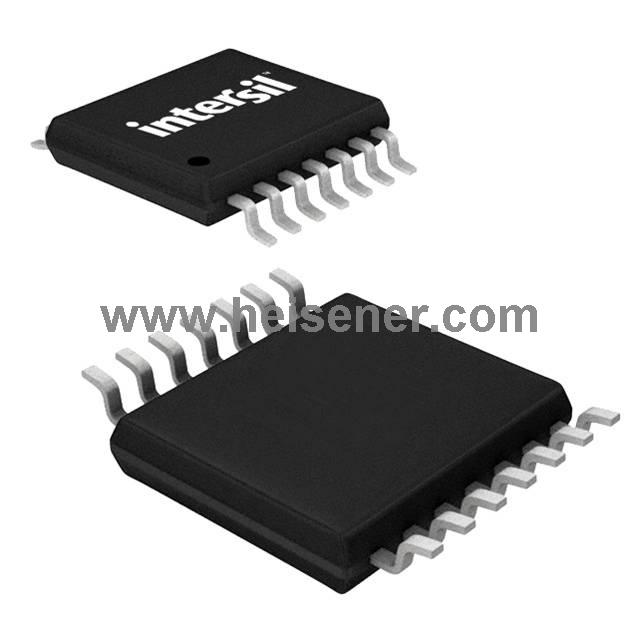
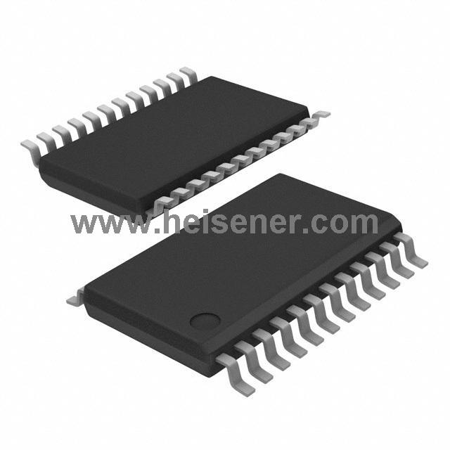
X9110 Pin Configuration

X9110 function block diagram
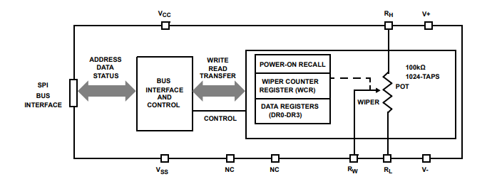
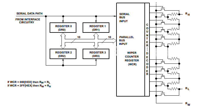
X9110 Detailed function diagram

Features
● 1024 resistance switch - 10 bit resolution
● SPI serial interface for write, read, and transfer operations potentiometer
● Wiper resistance, 40Ω typical at 5V
● Four non-volatile data registers
● Non-volatile storage for multiple wiper locations
● Recall the power-on and power on the load saving wiper
● Standby current Max. 5µA
● System VCC: 2.7V to 5.5V operation
● Analog V+/V-: -5V to +5V
●100kΩ end-to-end resistance
● Data is stored for 100 years
● Persistence: 100,000 data changes per register
●14 Ld TSSOP
● Dual supply version of X9111
● Low power CMOS
● Lead-free (RoHS compliant)
Applications
Circuit level application
● Change the gain of the voltage amplifier
● Provide a programmable DC reference voltage for the comparator Sum detector
● Control the volume of the audio circuit
● Trim the bias voltage error in the voltage amplifier circuit
● Set the output voltage of the voltage regulator
● Trim resistance in Wheatstone bridge circuit
● Control the gain, characteristic frequency and q factor of the filter circuit
● Set the scale factor and zero of the sensor signal Regulating circuit
● Change the frequency and duty cycle of the timer ic
● Change the DC bias of the pin diode attenuator in the RF circuit
● Provide a control variable (I, V or R) in the feedback circuit
System-level application
● Adjust the contrast of the LCD
● Control the power level of the LED transmitter in communication system
● Set and adjust the DC bias of the RF power amplifier in a wireless system
● Control the gain of audio and home entertainment systems
● Provides variable DC bias for tuners in RF wireless systems
● Set the operating point of the temperature control system
● Control the operating points of sensors in industrial systems
● Correcting offset and gain errors in AI systems
Device description
Series interface
The X9110 supports SPI interface hardware conventions. The device is accessed via SI input and the data is clocked on the rising SCK. CS must be LOW and the HOLD and WP pins must be HIGH throughout the operation. SO and SI pins can be linked together because they have three state outputs. This helps reduce the number of pins in the system.
Distributed array description
The x9110 consists of an array of resistors. The array contains the equivalent of 1023 discrete resistance segments in series. The physical end of each array corresponds to the fixed terminals (rh and rl inputs) of the mechanical potentiometer. Between the ends of each array and each resistance segment is a cmos switch connected to the wiper (Rw) output. In a single array, only one switch can be turned on at a time. These switches are controlled by a wiper counter register (WCR). The 10 bits of WCR (WCR[9:0]) are decoded to select and enable one of 1024 switches. Detailed block diagram is shown below
Detailed potentiometer block diagram